Flexible Shaft Coupling
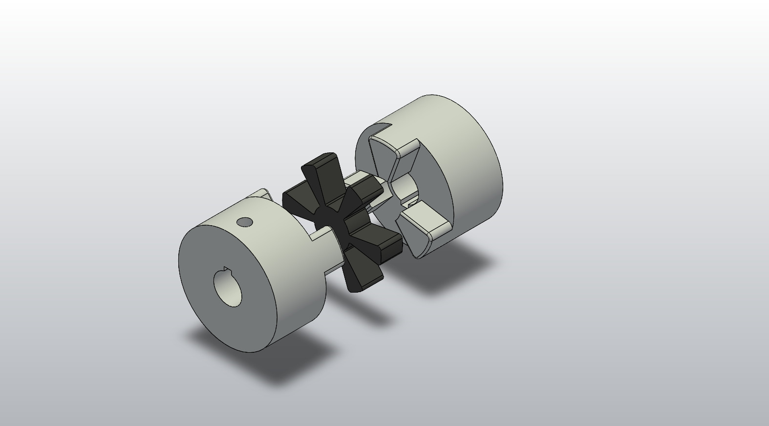
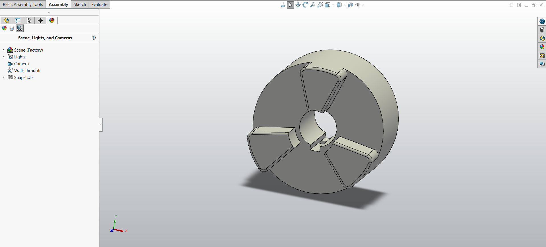
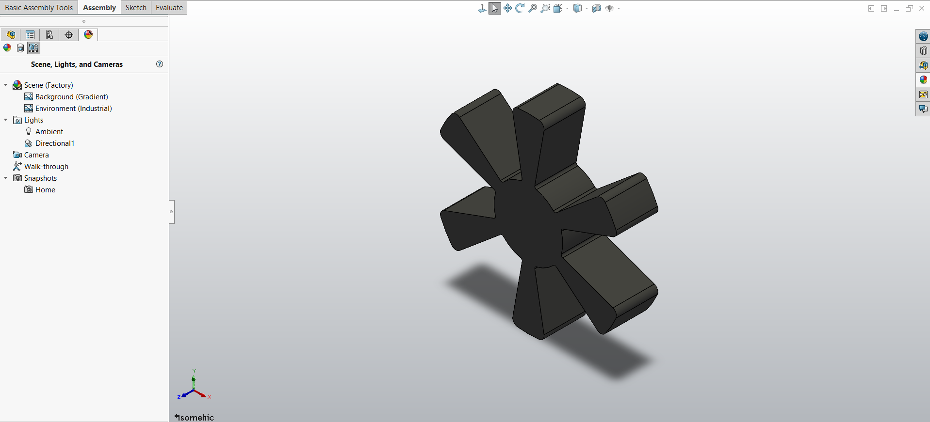
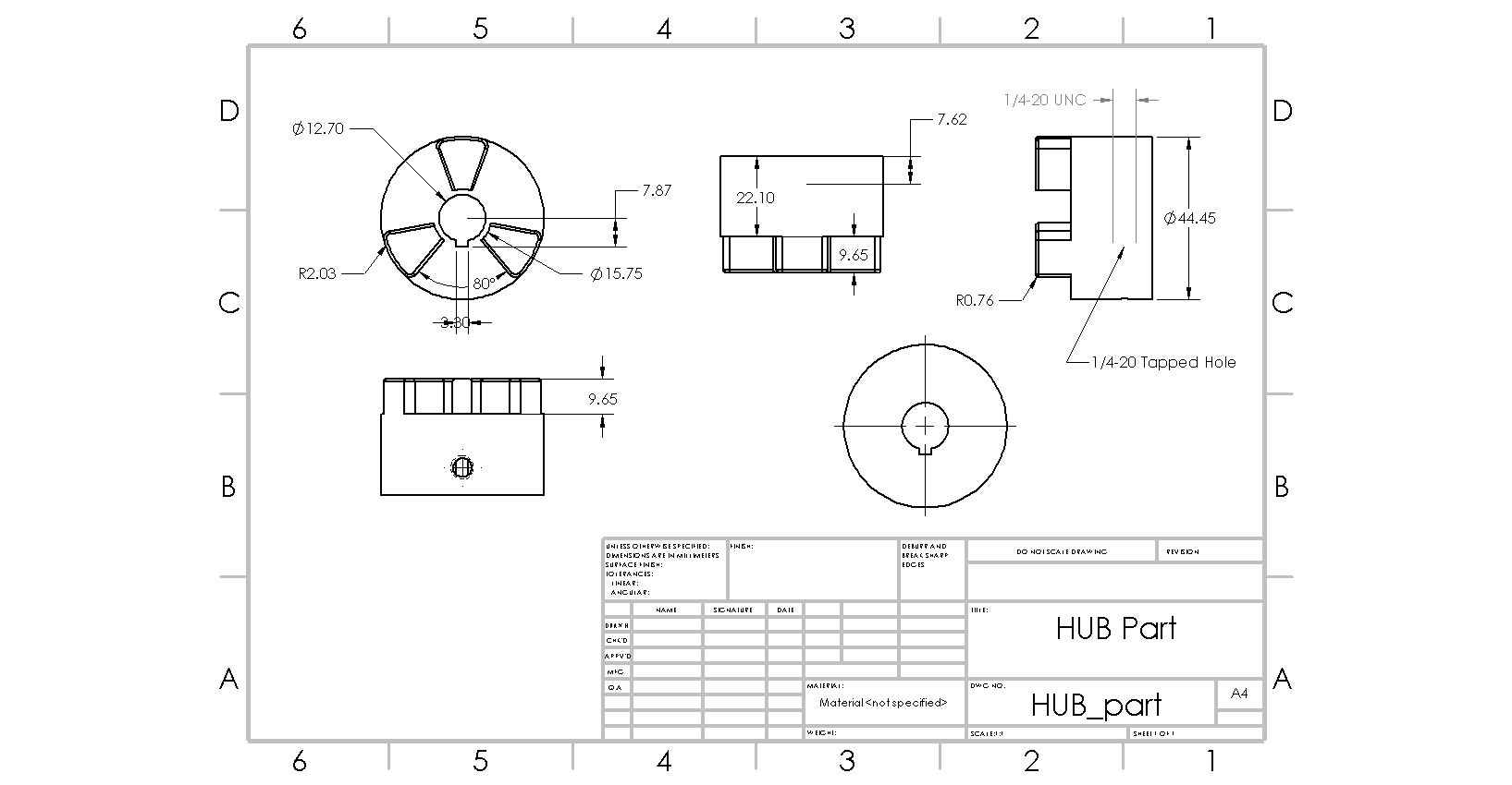
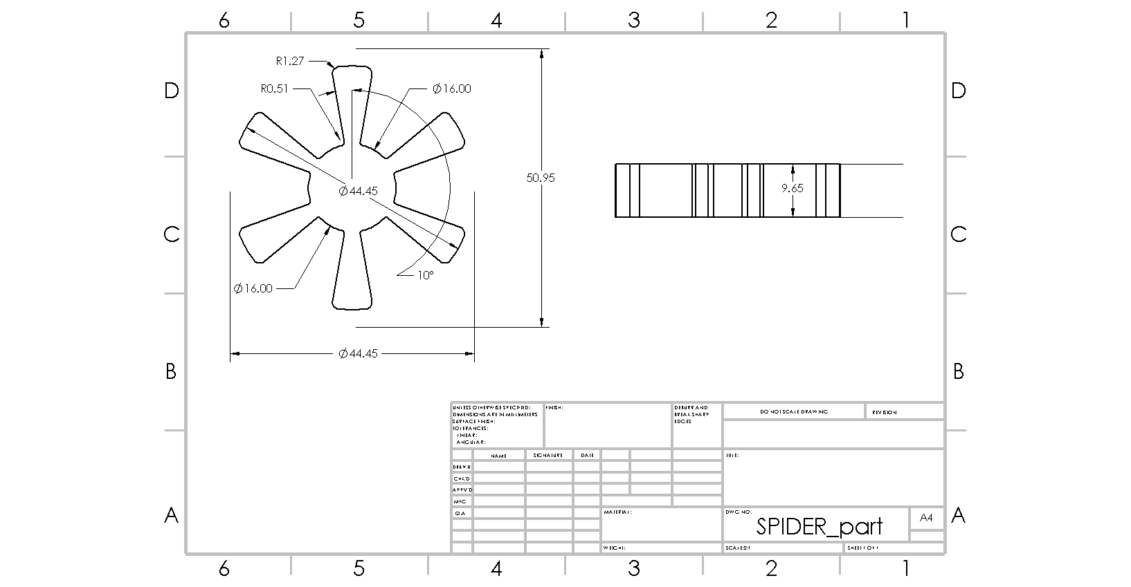
A jaw-type flexible shaft coupling designed in SolidWorks, from 3D parts to the full assembly and dimensioned manufacturing drawings. The coupling is made of three parts: two hubs of the same design and a six-lobed flexible spider. Each hub has a ½ in (Ø12.70 mm) bore with a keyway and a 1/4-20 UNC tapped hole for a set screw, so it locks onto its shaft and cannot slip under torque. The hubs' interlocking jaws sit around the spider, which fills the gaps between them: torque passes from one shaft to the other through the spider's lobes, not through metal-to-metal contact. The exploded view shows how the three parts stack together along the shaft axis. The two part drawings give the detail needed to make them: a Ø44.45 mm outer diameter, a 9.65 mm jaw height matching the 9.65 mm spider thickness, radii, angles and the tapped-hole callout. The dimensions follow standard inch sizes (½ in bore, 1¾ in outer diameter). Where it is used: this type of coupling connects a motor shaft to the machine it drives, such as pumps, fans, compressors, conveyors, gearboxes, mixers and small machine tools. Because the spider is flexible, it absorbs shock and vibration, tolerates small angular, parallel and axial misalignment between the two shafts, and protects the bearings and the motor from sudden load changes. It is also the intended wear part: when the spider ages, it can be replaced while the hubs stay mounted on the shafts, which keeps maintenance quick.